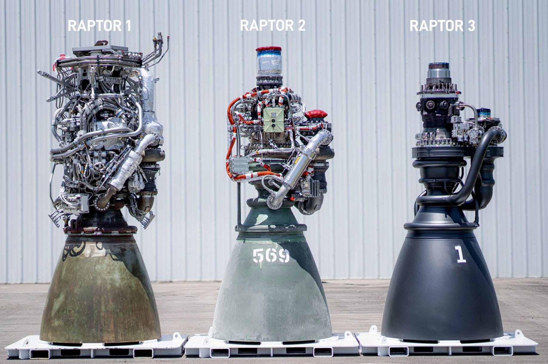
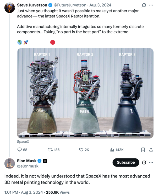
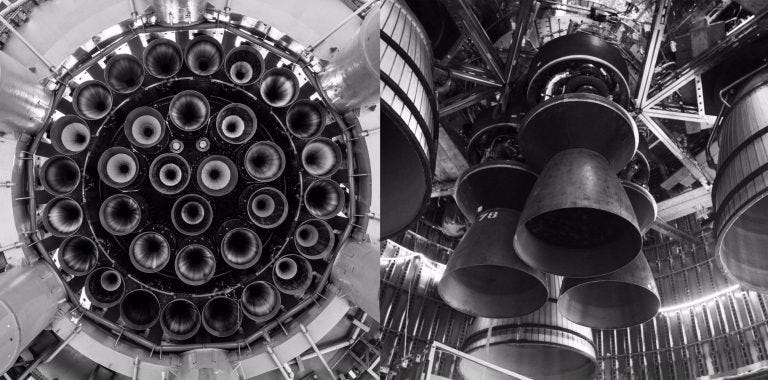
If you’re reading this, there’s a very good chance you’ve seen this famous image of three iterations of SpaceX’s Raptor rocket engine. The Raptor engine was developed for SpaceX’s Starship spacecraft (the Falcon 9 and Falcon Heavy use the Merlin engine); it was first test-fired in 2016, first flew on Starhopper in 2019, and first flew on a Starship prototype in 2020 and on the full Starship stack in 2023. Since then, it’s continued to improve, going from the tangle of pipes and wires you can see on the Raptor 1 to the smooth, streamlined design of the Raptor 3, which first flew in May of this year.
The evolution is so dramatic that many folks initially believed that it wasn’t real; Tory Bruno, the then-CEO of space launch company United Launch Alliance, tweeted that there was “no need to exaggerate this by showing a partially assembled engine,” which was followed by SpaceX president Gwynne Shotwell tweeting a picture of the Raptor 3 firing successfully:
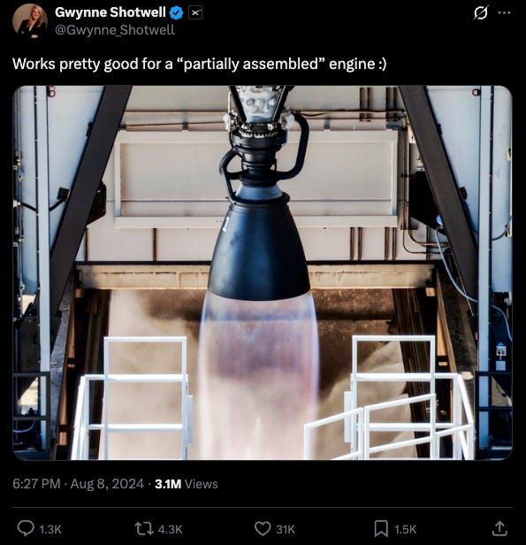
This streamlining has come alongside meaningful gains in performance, with the Raptor 3 providing about 35% more thrust than the Raptor 1.
I wanted to better understand how this evolution actually happened. What, specifically, did SpaceX change that allowed it to go from the tangle of wires and pipes to the svelte, streamlined engine on the right?
There turned out to be less detail available here than I hoped. SpaceX doesn’t publish any official Raptor schematics, and no one has done a teardown of a Raptor engine. But thanks to the occasional comment from Elon Musk, and the speculations of an army of SpaceX fans, we can get some idea of what the major changes have been.
How the Raptor engine works
The Raptor engine is a “full-flow staged combustion” (FFSC) engine. What exactly does that mean?
A rocket engine works by throwing mass (“propellant”) out of a rocket nozzle — due to Newton’s Third Law (“for every action there is an equal and opposite reaction”), this pushes the rocket in the other direction. The more mass you can throw out, and the faster you throw it, the more thrust your rocket engine will produce.
The simplest way to do this is to simply fill a tank full of pressurized gas, and vent some of the gas out. The venting gas propels the rocket, in the same way that letting the air out of a balloon pushes the balloon. This sort of rocket, called a “cold gas thruster,” is often used for making minor adjustments to a spacecraft’s position or orientation. Cold gas thrusters are found on, among other equipment, NASA’s Manned Maneuvering Unit, and the control thrusters for SpaceX’s Falcon 9 rocket.
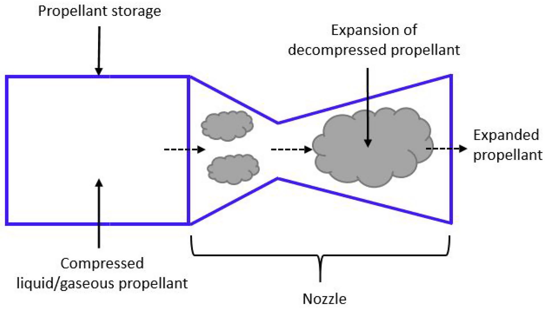

These engines are simple and reliable, but limited; there’s only so much thrust you can practically get from a cold gas thruster. So how can we get more thrust? One obvious way is instead of a single propellant, we can use two: take a fuel (like kerosene) and an oxidizer (like oxygen) and then burn them together in a combustion chamber, creating hot gas that escapes out the back of your rocket nozzle. Now instead of just using the energy stored in the pressurized propellants, we’re also using the energy stored in their chemical bonds, and converting that energy into thrust. An engine that uses the pressure of the propellant tanks to force fuel and oxidizer into the combustion chamber is called a pressure-fed engine. The engine used for the ascent stage of the Apollo Lunar Module was this type of engine: it used nitrogen tetroxide (N2O4) as an oxidizer and a fuel called Aerozine 50, both pressurized.
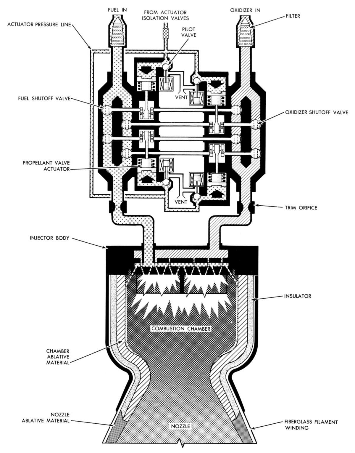
But now you have a problem. To prevent the burning gases in the combustion chamber from flowing back into the fuel and oxidizer lines (starving the combustion chamber of incoming propellant), the pressure in the combustion chamber has to be lower than the pressure in the fuel and oxidizer tanks and lines. But for a compact, powerful rocket engine, we want to have very high pressures in the combustion chamber. We could deal with this by increasing the pressure in our propellant storage, but this quickly gets impractical: the higher the pressures, the thicker and heavier our storage tanks and propellant lines need to be in order to maintain them without rupture. A better solution is to store the propellants at low pressure, and then feed them through a pump that increases their pressure before they reach the combustion chamber. This is the standard way to build a powerful rocket engine, and virtually every engine used for putting a rocket into orbit uses a pump of some kind to pressurize the fuel and oxidizer.
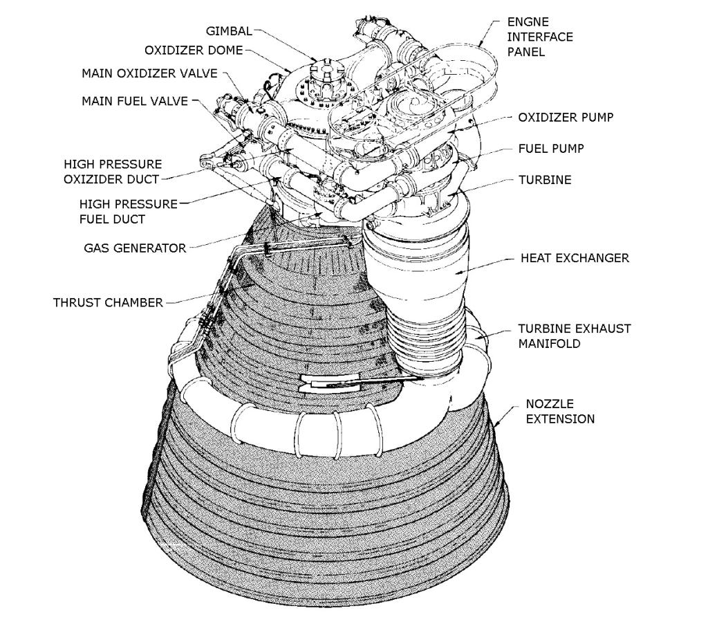
Now we have a new problem: because of the volume of fluid they must handle and the amount of pressure they must add, these pumps require an enormous amount of power to operate. The turbopump on the F-1 engine used on the Saturn V, for instance, required around 41 megawatts of power, slightly less than the power the S8G nuclear reactor delivers to the propeller shaft of an Ohio-class submarine. One way to provide this power is with a battery — Rocket Lab’s Electron rocket has an engine with a battery-powered electric pump — but the more common strategy, employed by virtually every large booster rocket, is to use the rocket’s own propellant as a power source, burning a small amount of fuel and oxidizer to drive a turbine that in turn drives the pump.
There are different ways that a system like this can be configured. The simplest is to route a small amount of fuel and oxidizer to a turbine, and then vent the resulting exhaust. This is known as a gas generator cycle, and it’s what’s used on the F-1 engine, as well as SpaceX’s Merlin engine.
Another option is to burn some of the fuel and oxidizer to drive the pump, but then route the burned propellant through the main combustion chamber along with the unburned fuel/oxidizer. This is known as “staged combustion,” and the smaller combustion chamber used to drive the pumps is called the “preburner.” This is a more complex arrangement than a gas generator cycle, but it’s also more efficient, since the hot exhaust that drives the turbopump isn’t just wastefully vented.
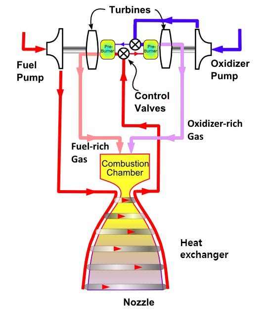
For most staged combustion engines, only a portion of the propellant gets routed through the preburner: the rest gets routed around and goes directly to the combustion chamber. But SpaceX’s Raptor uses a particular type of staged combustion known as “full flow.” In a full-flow engine there are two preburners, one that drives the fuel pump and one that drives the oxygen pump. All the propellant gets routed through the preburners: in one of them, a small amount of oxidizer is burned in the presence of a large amount of fuel (leaving most of the fuel unburned), while in the other a small amount of fuel is burned in the presence of a large amount of oxidizer (leaving most of the oxidizer unburned). The fuel-rich and oxidizer-rich exhaust streams then both enter the main combustion chamber, where they’re burned together.
A full-flow staged combustion engine is very complex, and prior to the Raptor only two had been built, neither of which successfully flew on a rocket. The Russians developed an FFSC engine in the 1960s, the RD-270, but it never flew, and the US built part of an FFSC engine called the Integrated Powerhead Demonstrator in the 1990s and 2000s, but it was never developed into a full engine. (When SpaceX began working on the Raptor in 2012, it obtained some of the equipment used on the Integrated Powerhead Demonstrator.) But an FFSC engine has several advantages, one of which is (theoretically) reliability: because so much mass flows through the turbines driving the pumps, the turbines can run cooler and at lower pressure, making them (in theory) more reliable. If you’re a company betting heavily on reusable rockets, a more reliable turbine is obviously attractive.
How the Raptor evolved
SpaceX is, understandably, tight-lipped about many of the specifics of its advanced rocket technology, and there’s less official information on the exact details of how the Raptor operates than you might hope. Nobody has opened up a Raptor engine to show what’s inside, and much of the information that exists comes from Elon Musk’s tweets or his comments in Everyday Astronaut interviews.
There are, however, a lot of SpaceX enthusiasts out there, many of whom do things like obsessively photograph every Raptor engine leaving the factory, and these folks have put a lot of effort into speculating about how the Raptor engine works. The most useful output of this speculation, for me, is the various fan-made schematics that show how the Raptor engine is thought to operate. These schematics aren’t official — they’re made by SpaceX enthusiasts piecing together information from various sources — so they must be taken with a large grain of salt. But they’re still a useful starting point for getting an idea of how people think various versions of the Raptor engine have worked.
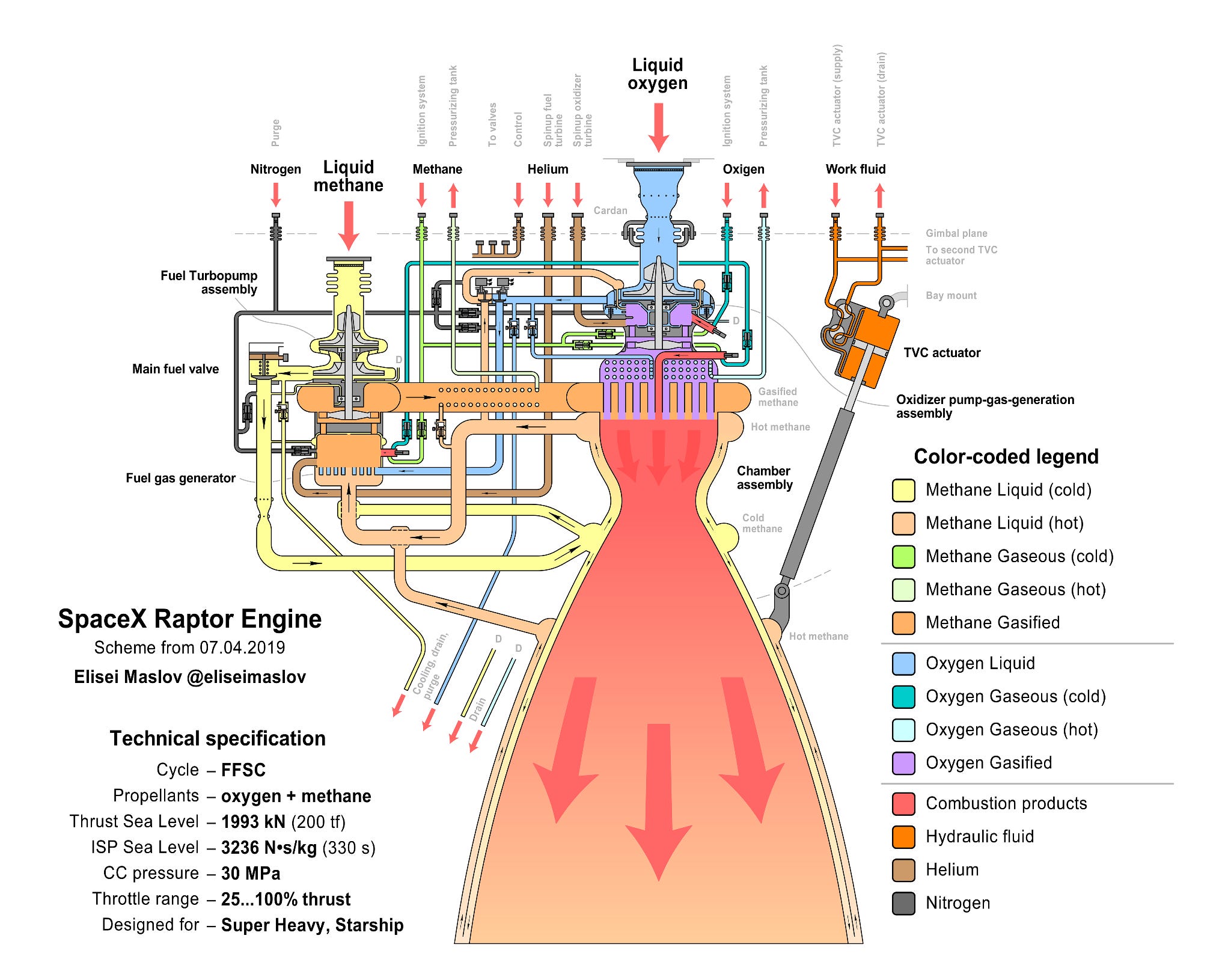
To start, let’s look at some schematics of version 1 of the Raptor. The image below was created by Elisei Maslov, a Russian propulsion engineer, in 2019.
Another useful Raptor version 1 schematic is the one below, created by NASASpaceFlight forum member “hisdirt” in December 2019. This is particularly useful because it calls out the various engine components on an actual 3D model of the engine (modeled in Revit, of all things).
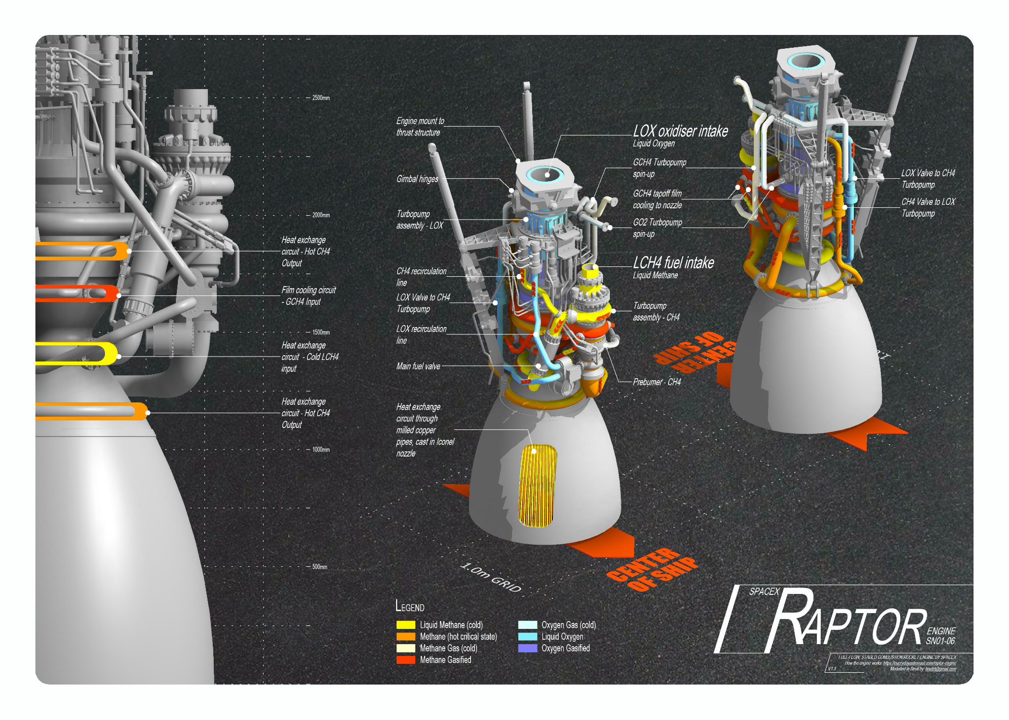
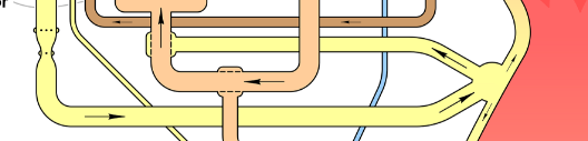
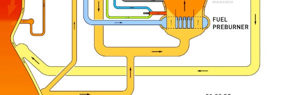
You can see in these schematics the basic components of a full-flow staged combustion engine: the oxygen pump, turbine, and preburner are on top of the engine, while the fuel pump, turbine, and preburner are the assembly on the side. You can also see how the fuel flows through the outside of the nozzle before going back into the preburner — this cools the nozzle so it doesn’t melt from the heat of the rocket exhaust, and is known as regenerative cooling.
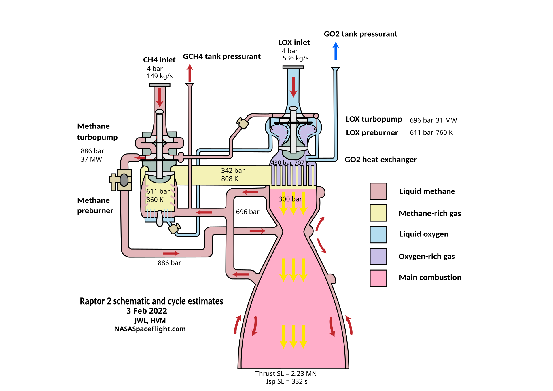
The next schematic, made by NASASpaceFlight users “Livingjw” and “HVM” in February of 2022, is from Wikipedia, and it shows version 2 of the Raptor. This is less detailed than Maslov’s schematic — it basically just shows the flow of oxygen and methane — but it shows the same basic arrangement: oxygen pump assembly on the top, fuel pump assembly on the side.
And this schematic, posted by Twitter user “TheSpaceEngineer” in January 2025, shows version 3 of the Raptor.
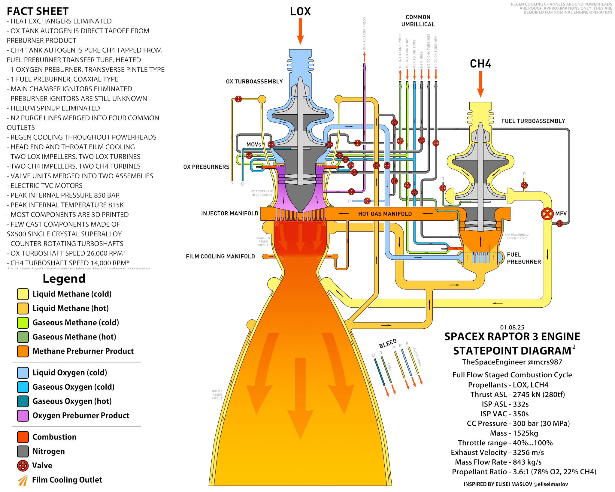
Assuming that these schematics aren’t grossly misleading, we can see that the major architecture hasn’t changed between version 1 and version 3 of the engine. It’s still a full-flow staged combustion engine, and still has the basic arrangement of the oxygen pump, turbine, and preburner assembly on the top, with the fuel pump, turbine, and preburner mounted to the side, with fuel being used to regeneratively cool the nozzle. And you can see that a lot of the smaller lines are the same on versions 1 and 3. Both show nitrogen lines used for purging (clearing propellant out of the system), both show fuel and oxidizer lines going to the igniters, and both have fuel and oxidizer lines carrying gaseous propellant back to the tanks to keep them pressurized as they empty (this is known as autogenous pressurization).
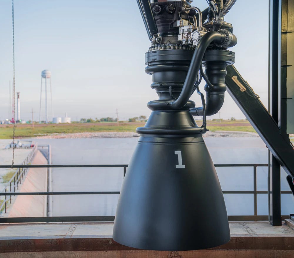
So what changed? If we look closely at the version 1 and version 3 schematics (remembering again that these are unofficial and speculative), we can see a few differences. Version 3 shows the smaller lines bundled together in a “common umbilical,” and if we look at photos of the Raptor 3 connected to a rocket we can see this:
The version 1 schematic also shows helium being used to spin up the fuel and oxygen turbines initially, while in version 3 these lines have been eliminated, and nitrogen is used instead. (It’s not amazingly obvious to me if this evolution is correct — some Reddit commenters on the version 1 schematic stated that helium wasn’t used — but there’s some evidence that it is.) Per these schematics, the helium used to control some valves present on version 1 is also absent on version 3, and the version 3 schematic shows no helium lines whatsoever.
The version 3 schematic also notes that a heat exchanger has been eliminated, something echoed by various folks on the NASASpaceFlight forums — this appears to be a gaseous oxygen heat exchanger near the preburner. There’s also a fuel line going to the preburner that’s present on version 1 but is absent on the version 3 schematic.
The more reliable source of changes, of course, is statements by Elon Musk and SpaceX. A 2022 NASASpaceFlight article about SpaceX’s update on the Starship progress noted that “everything from turbomachinery to chamber nozzle to electronics” was redesigned on Raptor 2, the turbopump had shrunk, and the preburner controllers “had been moved to boxes rather than being all over the engine.” An Everyday Astronaut article about the same update also notes that “many valves were combined into valve plates.” In a recent response to a September 5 tweet by Yishan Wong, the former CEO of Reddit, Musk ran down a short list of changes in the Raptor over time:

One big category here is sensors, and the various wires and cables they require. From what I understand, Raptor version 1 was in large part a development engine, and thus required a lot of extra sensors monitoring things like temperature and pressure in various parts of the engine to determine how it was behaving. As the engine got dialed in, a lot of these sensors could be eliminated (though some of them may have been moved internally).
Another thing Musk calls out is the main chamber spark igniters. Igniters, per their name, ignite the fuel and oxidizer in the main combustion chamber. These were present in version 1 of the Raptor, but by version 2 they had been eliminated. Musk doesn’t say what they were replaced with, but this change may have something to do with the fact that the hot fuel and oxidizer exhaust streams from the preburners probably need very little encouragement to combust. (A NASASpaceFlight comment from 2019 wonders if main chamber igniters are even necessary, given the high temperature of the preburner exhaust streams.)
Musk also notes that a lot of bolted flange connections were replaced by welded connections, reducing mass and joints that can leak at the expense of serviceability. This appears to be still taking place, as early Raptor 3 photos show a large bolted flange on the main body of the engine that in later photos has been eliminated:
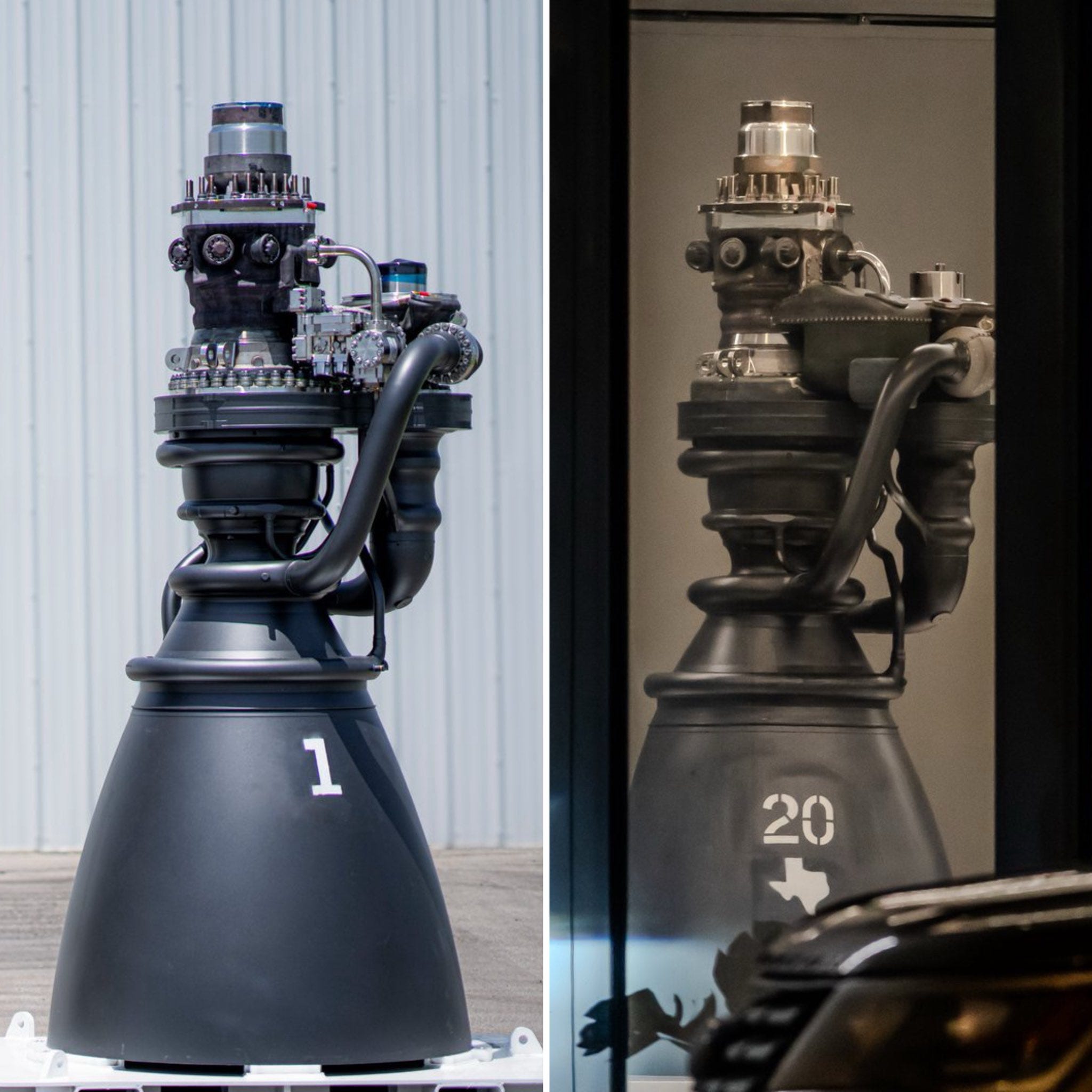

Another substantial change on Raptor 3 is that much of the piping hasn’t been eliminated, but moved internally, by way of 3D printing many of the components (Musk has previously noted that SpaceX “has the most advanced 3D metal printing technology in the world,” and in 2024 the company licensed the 3D metal printing technology of Velo3D).
Close-up photos of the Raptor 3, in fact, appear to show 3D printing lines:
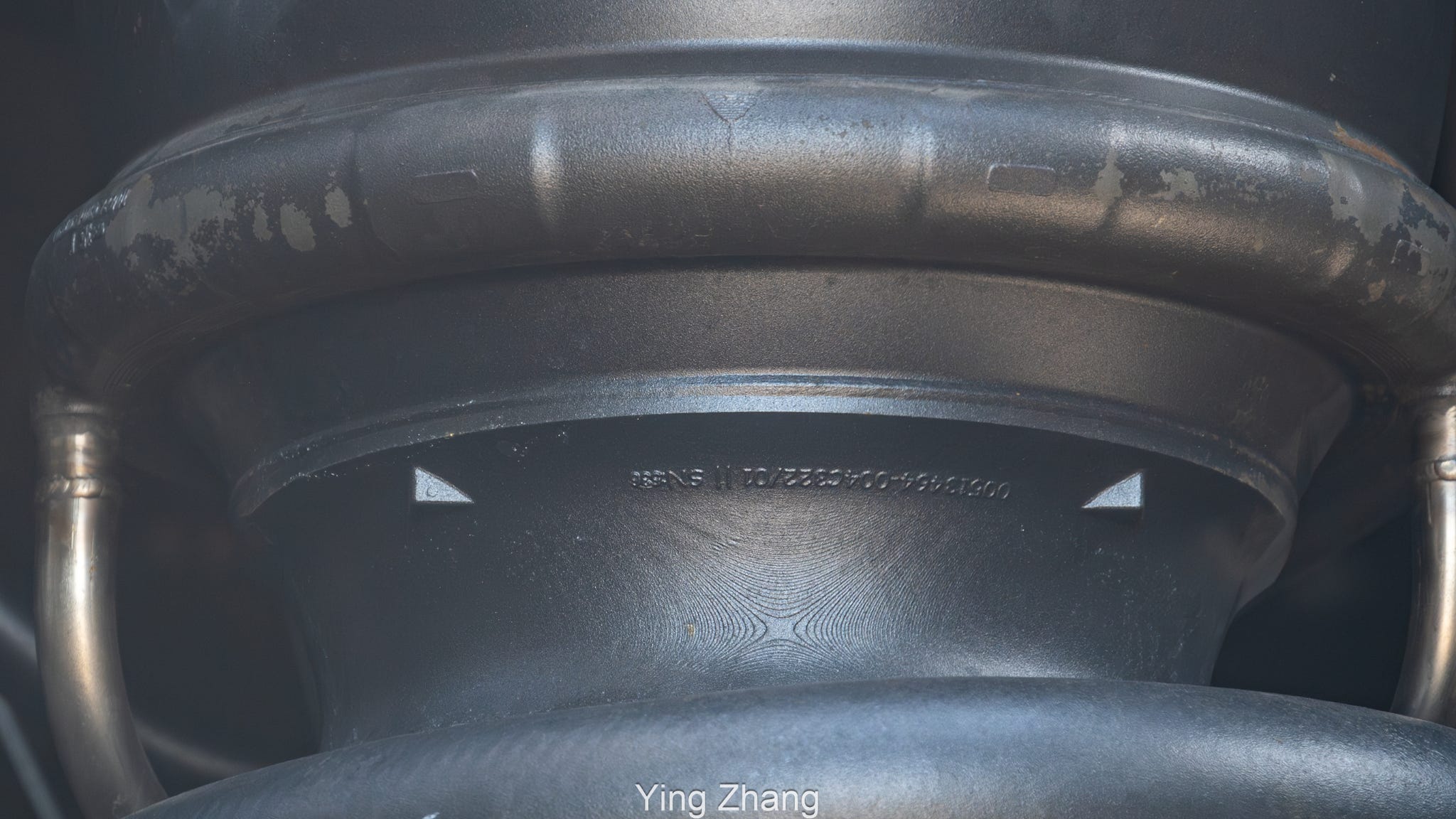
The purpose of this internalization is the removal of more parts, in particular the heat shield and fire suppression systems. The huge mass of wire and pipes on version 1 and version 2 of the Raptor required a large, heavy heat shield to protect it from the heat of the rocket exhaust. Internalizing the various propellant lines and adding internal cooling systems allows this heat shield and fire protection system to be eliminated. In fact, the biggest mass change from version 1 to version 3 of the Raptor comes from mass removal of “vehicle side” engine hardware, which is almost certainly largely the heat shield.

Conclusion
SpaceX’s Raptor engine has undergone impressive evolution, going through several major versions, a dramatic increase in performance, and a dramatic decrease in mass and external components in a short amount of time. The fundamental architecture of the engine hasn’t changed — it’s still a full-flow staged combustion engine, using the same primary components — but the various ancillary elements and components supporting its operations have been modified significantly.
It’s worth noting that while this streamlining has made the Raptor engine simpler in the sense that various individual parts have been eliminated, it was still an (as Musk notes) enormously complex task to get it to work, and there’s a huge amount of internal complexity added to the Raptor 3 that these pictures don’t show. And the problems haven’t been completely ironed out: the first launch attempt of Starship’s flight test 13 was aborted automatically by the vehicle’s flight software at T-0 (right before liftoff) this past July when several Raptor 3 engines failed to start. So the picture of several versions of the Raptor is a snapshot of a piece of technology that’s continuing to evolve.